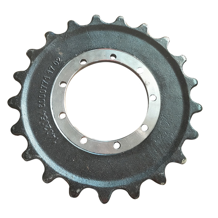
In Drive Sprocket, how to determine the number of teeth size?
According to the size of the chain speed, the calculation method of chain drive has the following two kinds:
1. Medium and high speed chain drive (v≥0.6m/s) design calculation steps: chain in medium and high speed conditions, may occur wear, chain plate fatigue damage, roller and sleeve pitting and sleeve and pin bonding failure, so should be calculated according to the power curve design. (1) Select the number of sprocket teeth z 1, z
2. In order to reduce the uneven movement and dynamic load, the number of teeth of the small sprocket should not be too small, usually z min =17 (at least to 9 when the chain speed is very low), can be selected according to the chain speed Table 9-6 z
(1). The number of big wheel teeth z 2 = iz 1, z 2 should not be too much, z 2 too much not only increase the size and weight of the drive, and chain elongation prone to tooth jumping and chain off phenomenon, usually z 2max <120. In order to make the chain wear uniform, the general number of chain section L p is even, the number of sprocket teeth is odd. General transmission ratio i≤7; i=2.0 ~ 3.5 is recommended, and i can reach 10 at low speed and steady load. If i is too large, the package Angle of the chain on the small sprocket will be reduced, the number of gear teeth will be reduced, and the wear of gear teeth will be accelerated. Table 9-6 Teeth of the driving wheel driven by a roller chain z 1 Chain speed v (m/s) 0.6 to 3 3 to 8 > 8 z 1 ≥15 to 17 ≥19 to 21 ≥23
(2) Initial center distance a 0. The center distance a is small, the structure is compact, but the number of chain links is small. When the chain speed is constant, the stress cycles of each chain link in unit time increase, which accelerates fatigue and wear. Center distance a large, chain number, long service life, but the structure size increases. When the center distance is too large, it will make the chain loose edge hanging too large, vibration, so that the stability of the transmission is reduced. Generally, a 0 =(30 ~ 50)p (9-5) a max = 80p, and a 0 can be greater than 80p when the tensioning device is used.
(3) Determine the chain pitch p. The relationship between the power P transmitted by the chain drive and the rated power P 0 of the chain under specific conditions is as follows: P 0 ≥ (9-6), where K A is the working coefficient of the chain drive, as shown in Table 9-7; K Z is the coefficient of the number of teeth of the small sprocket, that is, the coefficient when z 1 ≠19 is considered, as shown in Table 9-8. When the working area of the chain drive is on the left of the apex of the rated power curve (FIG. 9-8), check K Z and K Z 'on the right. K m is the multi-row coefficient of the chain, as shown in Table 9-9. Type of load Working machinery Examples Prime mover motor or steam turbine Internal combustion engine load stable liquid mixer, centrifugal pump, centrifugal blower, textile machinery, light transport, chain transport, generator 1.0 1.2 Medium impact General machine tools, compressors, woodworking machinery, food machinery, printing and dyeing textile machinery, general paper making machinery, large blowers 1.3 1.4 Large impact forging machinery, mining machinery, engineering machinery, oil drilling machinery, vibration machinery, rubber mixer 1.5 1.7 Table 9-7 Working conditions of chain drive coefficient K A According to Formula 9-6, P 0 and the speed of the small sprocket n 1 are obtained. The model and pitch p of the chain are shown in Figure 9-8. On the premise of satisfying the transmission power, the pitch should be as small as possible. For high-speed (v>8m/s) heavy - duty chain drive can be selected bar distance multi - row chain. Table 9-8 Tooth coefficient of the sprocket K Z Z 1 17 19 21 23 25 27 29 31 33 35 K z K z '0.887 0.846 1.00 1.00 1.11 1.16 1.23 1.33 1.34 1.51 1.46 1.69 1.58 1.89 1.70 2.08 1.82 2.29 1.93 2.50 Table 9-9 multi-row coefficient K m row 1 2 3 4 K m 1.0 1.7 2.5 3.3
(4) Check the chain speed v to determine the lubrication mode. The calculated value of chain speed is (9-7) v should conform to the range of chain speed assumed when z 1 was selected, and the lubrication mode is determined by Figure 9-9. Figure 9-9 Recommended lubrication methods.
(5) Determine the number of links L p. The calculated value of the number of chain links L p is (9-8). The calculated L p should be rounded into a close integer and as even as possible.
(6) Calculate the actual center distance a. According to Formula 9-8: mm (9-9) In order to make the loose edge of the chain have a reasonable sag, so as to facilitate the smooth meshing between the chain and the sprocket, the actual center distance should be 2 ~ 5mm smaller than the theoretical center distance A during installation.
(7) Calculate the axial pressure F Q. Axial pressure is calculated as follows: (9-10), where: is the circumferential force borne by the chain, N. (8) Calculate the size of sprocket end face and shaft surface, and draw the sprocket working diagram. The end dimensions of the sprocket are calculated from Table 9-2, and the axial dimensions of the sprocket are calculated from Table 9-4. According to the size of the drawing, and indicate the standard tooth shape, tooth number and pitch. 2. Static strength calculation of low-speed chain drive (v<0.6mm) : for low-speed chain drive, its main failure form is overload breaking, so it should be calculated according to the static strength, and check the safety factor of its static strength s, that is, ≥4 ~ 8: F Q is the ultimate tensile load of a single row chain (see Table 9-1); m is the number of chain rows.
 English
  Español
  Português
  русский
  Français
  日本語
日本語  Deutsch
  tiếng Việt
  Italiano
  Nederlands
  ภาษาไทย
  Polski
  한국어
한국어  Svenska
  magyar
  Malay
Malay  বাংলা ভাষার
  Dansk
Dansk  Suomi
Suomi  हिन्दी
  Pilipino
  Türkçe
  Gaeilge
  العربية
  Indonesia
  Norsk
Norsk  تمل
تمل  český
český  ελληνικά
  український
  Javanese
  فارسی
فارسی  தமிழ்
தமிழ்  తెలుగు
  नेपाली
  Burmese
  български
  ລາວ
ລາວ  Latine
  Қазақша
  Euskal
  Azərbaycan
  Slovenský jazyk
  Македонски
  Lietuvos
  Eesti Keel
  Română
  Slovenski
  मराठी
मराठी  Srpski језик

